
Here is my new winter project: http://qrp-labs.com/qcx.html
I couldn't resist buying this little 10 x 8 cm gem with a lot of features for just 49 $
The two SMD ICs are already factory pre-soldered.
Compleet unit size incl. spacers : 101.6mm x 81.3mm x 34mm.
A little gem needs a nice encclosure.
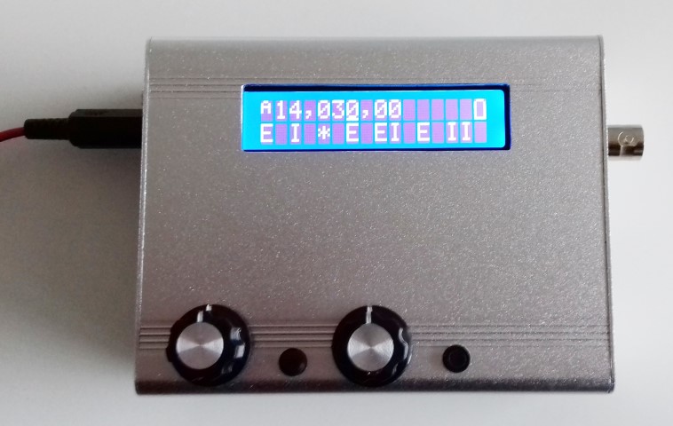
A nice 110x88x38mm enclosure for this transceiver can be found on eBay : Link
The grooves for the pcb are not used and have to be reduced about 2mm near the volume potentiometer and the pcb pylons. Also the groove at the LCD side may touch the soldering pads of the LCD . The PCB is mounted on the original 12mm pylons. These pylons are held by countersunk headed bolts to the lower cover. So to open the enclosure, remove the two knobs and the upper 4 screws of the side panels. To prevent stress to the PCB , the huge plastic BNC connector is replaced by a metall chassis-mounted type. This will automatically ground the enclosure.😉
By means of a shaft extender the difference in height of the controls is matched.
Don't use the standard BNC connector from the kit. The PCB will be off centre.


 | |||
| Making markings for 3mm holes. |
 | |
| Making space for the potentiometer and pylons |
 | |
| Pylons fitted Removing the groove in the cover is verry easy. By carving into the alloy as the picture shows the material weakens and can be removed with a small srewdriver . |


 |
Perfect fit😎  |

At last the controls of the QRX are fixed. I had 2 extended push buttons in stock as wel as some cheap plastic potentiometers. The shafts were cut of and appeared to be hollow. A 1/8( 3mm) drill was used to enlarge the shaft inside for aprx. 2mm.
Next the shaft was pushed over the button’s shaft and fixed with superglue.